OSCILLATOR TEST FIXTURE
Recently I ran across a mention of Epson programmable oscillators in the rec.radio.amateur.homebrew newsgroup. I was aware that Digi-Key carried a series of crystal oscillators with programmable dividers, but the frequency choices are fairly limited. The SG-8002 programmable oscillators are a different animal, using phase-locked-loop (PLL) technology to generate any specified frequency between 1 and 125 MHz. To view the Digi-Key catalog page that describes the available versions of the SG-8002, go to the Digi-Key web site and search for "SG-8002".
Data sheets in pdf format can be downloaded directly from Epson at:
http://www.eea.epson.com/products/qd/qdcrystalosc.htm
The parts are available in surface mount, 14-pin or 8-pin DIP package footprints (the packages actually have only 4 pins). It wasn't clear from the data sheets just how closely you can specify the frequency, although if you follow the links on the Epson web site, there is a place where you can enter a desired frequency and it will tell you if it is valid. But there were still a lot of questions, like how close do they actually come to the specified frequency? Are they stable enough to put out a "clean" CW note on HF, or are they useful only as clock oscillators for digital circuits? How much phase noise? Since they are only $3.33 apiece, it doesn't cost much to find out (except that Digi-Key has a $5 service charge on orders under $25).
I ordered two oscillators, both with 8-pin DIP footprints, CMOS type, 50 ppm stability. One of the four pins on the package is either an "output enable" or "standby" pin, depending upon which option you specify. I ordered an 18.573000 kHz oscillator with the output enable option, and a 1.703915 MHz oscillator with the standby option. The 18-MHz part could be used with a 74HC390 dual decade counter to provide a square wave output at 185.730 kHz, which was chosen because it falls midway between 60-Hz harmonics. Although I don't have any plans to get back into MedFER operation, the 1.7 MHz part could be used to directly drive a MedFER final. The frequency of 1.703915 was chosen to be near the top of the expanded AM broadcast band, and is not a multiple of any common reference frequency like 10, 100 or 1000 Hz. The idea was to see if the oscillator could be programmed to the nearest 1 Hz increment. When I called Digi-Key, the person who took my order contacted the person who does the oscillator programming on another line, and verified that both frequencies were OK. The parts were shipped out the same day.
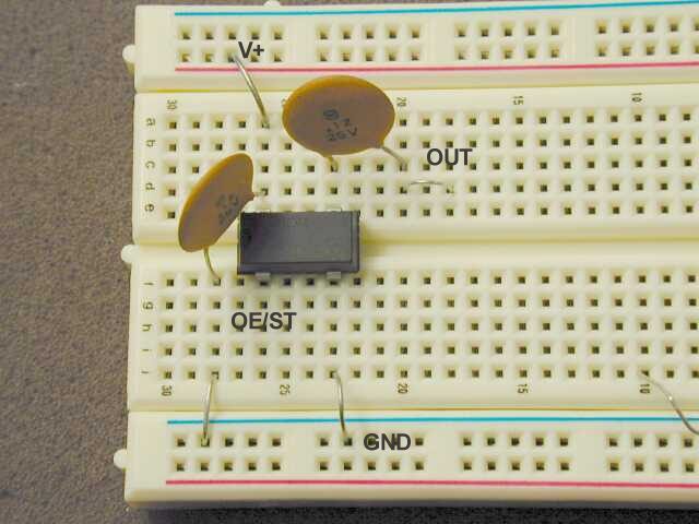
The elaborate fixture shown below was used to test the oscillators. People with soldering anxieties should find it comforting that the oscillators work fine on a plug-in protoboard, at least up to the 18 MHz region.
OSCILLATOR TEST FIXTURE
The DC supply voltage was applied to the points marked V+ and GND, and a scope/counter lead was connected to the OUT point, which is the oscillator output coupled through a 0.1 uF capacitor. Another 0.1 uF capacitor is used as a bypass between V+ and GND. If the OE/ST pin is left floating, the oscillator runs continuously. When it is grounded, the oscillator is either placed in STANDBY or OUTPUT DISABLE mode, depending on the chip option. The difference is that chips with the STANDBY option will turn off completely when OE/ST is grounded. In chips with the OUTPUT ENABLE option, the oscillator keeps running but the output stage is turned off. There apparently is an internal pullup resistor of a couple of megohms on the OE/ST line, because the current from the pin is only about 2 microamps when it is grounded. If you want to be able to shut off the oscillator with a logic-level signal and minimize power consumption while in the disabled mode, you would want a chip with the STANDBY option. For rapid on/off switching, as in a CW transmitter, you'd need the OUTPUT ENABLE option.
Here are the results of frequency versus supply voltage tests at room temperature.
Oscillator 1: Digi-Key Part No. SG-8002DC-PHB (8-pin DIP, output enable
option, CMOS, +/- 50 ppm)
Specified frequency: 1.703915 MHz
Oscillator 2: Digi-Key Part No. SG-8002DC-SHB (8-pin DIP, standby option,
CMOS, +/- 50 ppm)
Specified frequency: 18.573000 MHz
The normal operating voltage range for the CMOS versions is supposed to be 5.0 +/- 0.5 volts. As seen from the room temperature test results, at 5.0 volts the 1.7 MHz oscillator was off by only 2 Hz (approximately 1 part per million) from the specified frequency, and the 18 MHz part was off by 78 Hz (about 4 ppm). There is some sensitivity to supply voltage, which provides a very small amount of fine tuning capability. In both of these samples, it would be possible to reach the exact specified frequency by tweaking the supply voltage.
So far everything looks great, but what about the phase noise? A quick test was made by tuning in the 18 MHz oscillator on my IC-751A receiver. Coupling to the receiver was by means of a very short piece of wire connected to the end of a coax in the vicinity of the oscillator test board. I adjusted the coupling by moving the coax around until the received signal strength indication was S9 + 20dB when tuned to the oscillator frequency. The received note sounded very clean and stable, but there was definitely a lot of noise as I tuned away from the carrier. At this signal level, and with the receiver set to 500 Hz bandwidth, the oscillator noise was down to S6 at 5 kHz off frequency, and there was no reading on the S meter at 20 kHz off frequency (although some noise could still be heard in the speaker). From this crude test I would say that the 18 MHz oscillator is too noisy to use for anything but a very low power transmitter. It would be unacceptable in a high-performance receiver or converter application, because you'd hear the same kind of noise when tuned near any strong signal. Fortunately the phase noise in oscillators tends to follow a frequency-squared law, so that after dividing by 100 to get down into the LowFER band, the phase noise would be reduced by nearly 40 dB (not quite that much, because the division process isn't noise-free either). Should be adequate even for BPSK operation at MS100 (10 baud). Perhaps a 7-MHz Epson oscillator would be OK for a QRP CW transmitter running less than half a watt -- something I'll probably try some day. By the way, when the output is loaded with a 50 ohm resistor, the peak-to-peak voltage drops to about 4 volts (with a 5-volt supply). That's about 80 milliwatts of RF, most of it at the fundamental frequency of the square wave.
In the case of the 1.7 MHz oscillator, the phase noise drops off so rapidly that it is difficult to measure with normal receiver bandwidths. Using the IC-751A receiver in the wide (about 2.5 kHz) SSB mode, I obtained the audio spectrograms shown below with R. S. Horne's "GRAM" spectrogram program. GRAM was set for a sampling rate of 44 kHz, 16 bit resolution, 90 dB line type display with 10.8 Hz resolution and 128-sample averaging. The receiver was tuned slightly off the oscillator frequency to provide an 800 Hz "carrier" reference. For comparison, I also show the spectrum obtained with the receiver tuned to the output of the synthesized signal generator in my AILTECH FM-100 communications service monitor.
The 1.7 MHz Epson oscillator actually looks a little cleaner than the commercial synthesized generator, which apparently has some "reference frequency modulation". The spikes at 1600 and 2400 Hz are caused by harmonic distortion in the receiver's audio section. Why are there double spikes in the AILTECH harmonics? Beats the heck outa me!
At 18 MHz, the AILTECH generator looks the same as it did at 1.7 MHz. No surprise, because the voltage controlled oscillator in the AILTECH generator (which goes up to 999.999 MHz) is probably running above 1 GHz and being mixed down. The 18 MHz Epson oscillator is obviously much noisier, and there is little indication that the noise is ever going to fall off. It eventually does, of course, but that happens outside the 2.5 kHz bandpass of the receiver .
In conclusion, although they have their limitations, these oscillators
look great for LowFER and MedFER applications, and the price is hard to
beat for a "custom" crystal oscillator.
Lyle, K0LR