Audio Beacon Schematic
This project was inspired by Handi-Ham Student Coordinator Jerry Kloss, N0VOE. The Handi-Ham System is dedicated to helping people with disabilities enjoy the ham radio hobby, and is headquartered at the Courage Center in Golden Valley, Minnesota. Each year the Handi-Hams hold two week-long "Radio Camps"; one at Lake George, Minnesota in late August and one in Malibu, California at the beginning of March. These camps provide a week of fun and instruction for people wishing to obtain new licenses or upgrades, or to improve their operating skills. The camp in Minnesota is at a lakeside facility called Courage North, which has cabins, dining hall and activity buildings situated on about 90 acres of land. With trails winding among the pine trees, the camp is a perfect north woods setting -- but it's very difficult for blind campers to find their way around. Jerry's goal is to make the camp more "blind friendly", and these audible navigation aids were part of an experiment at the 2001 Minnesota camp. A total of five audio beacons were located at key trail intersections to provide reference points so that blind campers could find their way around the grounds independently. Here is a description of the units we used, which might be helpful in other applications.
The audio beacon units are designed to send a single-letter Morse identifier at a speed of approximately 10 WPM, repeated every two seconds. Two AA alkaline batteries will power the unit for more than two months of continuous operation. Housed in enclosures that are approximately 3.5 by 2.5 by 1.25 inches, the beacons were mounted on fiberglass electric fence posts for easy installation and removal. The diagram below is a schematic of the unit.
Audio Beacon Schematic
The circuit consists of U1; a 74HC14 hex inverting Schmitt trigger, and U2; a CD4017 divider/one of 10 decoder. U1A and U1B form a two-inverter oscillator that provides output pulses at a rate of just under 10 per second. These pulses are used to clock the 4017 divider/decoder. U1E and U1F also make up a two-inverter oscillator whose frequency can be varied by potentiometer R4. The adjustment range extends from about 700 Hz to frequencies above the audible range. Inverters U1D and U1E are the output stages, essentially providing a push-pull drive to the piezoelectric speaker SP1. That is, with 2.5 volts DC applied to the circuit, a peak-to-peak voltage of 5 volts can be delivered to the speaker. Potentiometer R6 is in series with the piezoelectric speaker to control the audio volume.
To program the desired identifier, diodes are soldered into the circuit board to connect the various outputs of U2, the CD4017 divider, to pull-down resistor R7. With no programming diodes in the circuit, R7 pulls the input of U1F close to ground level through D1, and disables the audio oscillator. If programming diodes are installed on the circuit board, the audio oscillator is enabled during the corresponding clock times. For example with diodes in positions 0, 2,3 and 4; the beacon puts out the Morse character "A". Only nine positions (outputs 0 through 8 of the CD4017) are available for programming diodes. The tenth position (pin 11, which is output 9) will force the CD4017's clock disable pin (pin 13) high for a period determined by C5 and R8. This produces a pause between repetitions of the identifier. Diode D2 protects the circuit from damage if the battery polarity is reversed. However, its primary purpose is to drop the voltage slightly; reducing the current drain and extending the battery life.
Because the piezoelectric speaker has a fairly sharp resonance at about 2 kHz, both the pitch and volume potentiometers will affect the sound level produced by the audio beacon. A fairly high output level occurs when the pitch is set to the low end of the range, at about 700 Hz, because the square-wave output has a large third harmonic near the 2 kHz resonant frequency of the speaker. Another, larger peak in intensity occurs when the pitch is actually set to 2 kHz. Average current drain of the circuit is about 0.3 milliamps. Current drain depends somewhat on the pitch setting; higher frequencies increase the battery drain.
The number of identifiers is limited by the fact that only nine diode positions are available. Using standard Morse element spacing, a "dit" uses one position; a "dah" uses three, and each silent period between dits and dahs also uses one position. Permissible identifiers are A, B, D, E, F, G, H, I, K, L, M, N, R, S, T, U, V, W, and 5. Other letters and numbers are too long to fit within the 9-element limit.
Locations of the components on the circuit board, including the "programming" diodes, volume and pitch controls are shown in the figure below.
Component Locations
All of the components can be mounted in a modified Radio Shack number 910-1105 enclosure (listed in the Radio Shack consumer catalog as part number RSU 11658101). In the first picture below, a quarter is included as a reference to show the size of the completed unit. It's a rather tight fit, as the subsequent inside view shows. In fact, it was necessary to carve away the PC board guides that are molded into the inner side walls of the box in order to make room for the battery holder and the PC board. I also drilled away two of the four circuit board mounting pedestals in the box, so that the PC board for the beacon could be attached directly to the inside front of the enclosure with double sticky Velcro fasteners. If size is not a consideration, a larger enclosure such as the Radio Shack number 910-4693 (RSU 12129771) provides a comfortable amount of room without modification. The third photograph is an inside view showing the components installed in the larger enclosure. Programming diodes are installed in positions 0, 1, 2, 4 and 6, which means that this unit sends the Morse letter "D". The piezoelectric speaker is mounted to the inside front of the case with double sticky tape. In the smaller enclosure, the speaker is under the batteries, and in the larger enclosure, the PC board is mounted on top of the speaker with double sticky Velcro fasteners. Because only a few units were built, I didn't use a commercially fabricated circuit board. Instead, I made the boards with the "iron on" technique. More details on the iron-on board fabrication technique are contained in my "All in one" transmitter article. Unlike all the stuff you see on TV, you can try this at home, and I will provide a laser printout of the board layout to anyone who wants to do so.
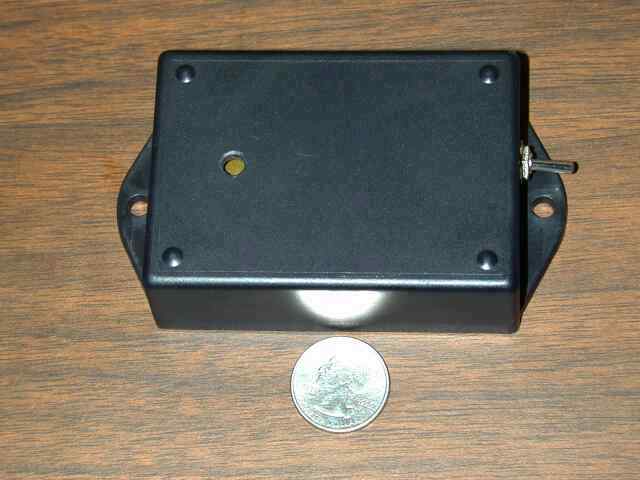
Completed Unit
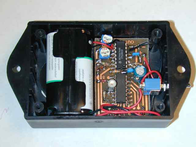
Inside View
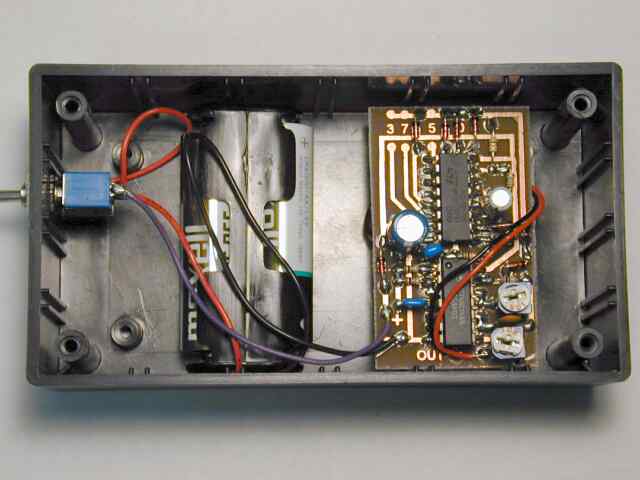
Inside View in Larger Enclosure
In most applications the beacons will be mounted outdoors. There is no simple way to make the units completely weatherproof, since it is necessary to have a hole in the enclosure for the sound to escape. For use at the Handi-Ham Radio Camp, the beacon units were mounted on short pieces of wooden boards, which had 3/8 inch holes drilled into the ends so that they would fit vertically on the top of 3/8 inch fiberglass electric fence posts (available at the local farm supply store). Weatherproofing was accomplished by tying plastic bags over the beacon units. Although the plastic bags did not attenuate the sound as long as they fit loosely over the beacons, there was a considerable reduction in output if the plastic directly covered the hole in front of the piezoelectric speaker. Apparently the plastic affects the resonant cavity that is part of the speaker housing. We fixed the problem by taping sticks to the front of the boxes so that the plastic could not come into direct contact with the front of the enclosure. A more elegant fix would be a simple wire cage around the entire box or in the vicinity of the speaker hole.
Motion Sensor Modification
In many applications it is unacceptable to have the beacon beeping 24 hours a day. One of the units for the Handi-Ham Radio Camp was modified to provide a motion sensor feature, so that it would be activated only when someone passes through the beacon location. An MS14A "Eagle Eye" indoor/outdoor wireless motion sensor from X10 Products www.x10.com was adapted for this application. The wireless feature of the MS14A is not needed, but this unit is convenient because it is battery powered and very compact. The diagram below is a circuit of the modified audio beacon.
The circuit has been modified by the addition of a 74HC14 hex inverter U3, NPN transistor Q1, resistors R9 and R10, and capacitors C6 and C7. Diode D2 is no longer used, and switch SW1 is replaced by a double pole, double throw switch with a center off position. This switch can be set to provide either continuous or motion-activated operation.
To adapt the MS14A motion sensor, two leads were tack-soldered to points on the circuit board which carry signal ground and the 3-volt pulses that trigger the unit's transmitter when motion is detected. I can't guarantee that the circuit board layout is the same for all production runs of the MS14A, but the points I used are shown in the photograph below.
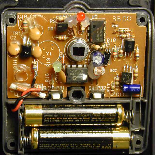
Connections to MS14A Motion Sensor
The red wire carrying the 3-volt pulses is soldered to the bottom of a 68-ohm resistor which I believe is labeled R1. Signal ground (black wire) is attached to the right side of a 6800 ohm resistor that may be labeled R2. (Component labels on the MS14A circuit board are directly under the resistors, and are very difficult to read without removing the parts.) I drilled a small hole in the back of the MS14A case so that the wires could be brought out to the audio beacon. Note: Since both the audio beacon and the MS14A operate from a 3-volt battery supply, it would be a simple matter to bring a wire from SW1 in the audio beacon and power the MS14A from the same AA cells used to operate the beacon. However, I left it running from its own internal AAA cells. It would also be possible to disable the wireless transmitter and perhaps extend the battery life, but I left the MS14A essentially unmodified except for the attachment of the two wires.
When motion is detected, pulses from the motion sensor are applied to the base of NPN transistor Q1 through the 10k resistor R10, causing the transistor to conduct and to discharge capacitor C6. The output of inverter U3A goes high, forcing the output of U3B low, and the paralleled outputs of U3C, D, E and F high. These outputs are connected to the 3 volt supply line of the audio beacon when SW1 is in the "motion" position. Capacitor C6 slowly charges through the 10 megohm resistor R9, and eventually the outputs of U3C through U3F go low and turn off the beacon. The amount of time that the beacon operates each time the motion sensor is triggered depends on the value of C6. With C6 equal to 3.3 microfarads, the beacon will operate for about 30 seconds. If the motion sensor is re-triggered during this period, the operating time is extended by another 30 seconds.
Note: the MS14A is normally used to turn on lights or other devices for a specified length of time, and will transmit an "off" signal after the specified period. The default is one minute. To keep the beacon from being triggered again automatically just after each activation (our simple circuit can't tell the difference between the coded "on" and "off" pulses), I recommend setting the MS14A delay to the maximum period of several hours, as detailed in its instruction manual.
Additional note: At the time of this writing, the regular price of the Eagle Eye outdoor wireless motion sensor was $24.99, although there are sometimes limited-time promotions and discounts, such as a second sensor for $1.